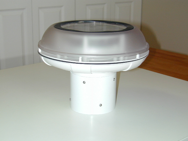
The shielding of the temperature/humidity sensor from solar heating (and nighttime radiative cooling) is rather poor. Because of this it must be placed in a location out of direct sunlight that is also shielded from the night sky. In addition it must be placed away from heat sources like walls and driveways to ensure accurate readings. In the current installation there was no suitable location available for the sensor. One way around the problem is to use a different enclosure that shields the sensor while allowing sufficient airflow through it to keep the sensor at the ambient air temperature. Such an enclosure was built out of a commercial solar-powered shed vent. This vent shields the sensor from direct sunlight while an internal fan draws ambient air across the sensor keeping it at the air temperature. The vent used is an ICP Solar Technologies "iSun SolarVENT" model 70430 shown below.
The vent fan is set to draw air in through the tube at the bottom and exhaust it through the slot around the periphery of the large-diameter top section. This unit contains a solar powered fan with 2 AA NiMH batteries to power the fan after sunset. The inlet tube was not long enough to contain the temperature/humidity circuit board so a 4" schedule 40 PVC coupler was used as an extension. This piece was a snug fit over the inlet tube and is held in place by four 1/2" sheet metal screws. Due to the internal battery housing the temperature/humidity sensor would not fit inside the opening. Its circuit board was thus removed from its housing and the housing trimmed to leave only the part necessary to hold the batteries. The modified circuit board is shown below.

Unfortunately the vent did not work well. The batteries would not power the fan after dark and the output of the solar panel appeared to decrease with time. About a week after installation power from the solar array was insufficent to power the fan during the day unless sunlight hit it at a 90 degree angle. The cause of the failure was not known but due to the modifications the unit could not be returned under warranty. To get around the problems the solar-powered fan was replaced with a hard-wired 92mm computer fan as shown below.
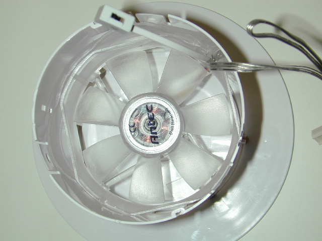
By removing the corners of the square fan housing with a coping saw the fan would slide into the inlet tube and rest against the original fan mount. Four screws (not shown) through the side of the inlet protrude into the tube just below the fan to keep it in place. The fan is powered by a 12V 500mA wall-wart. Since the solar cell was no longer needed it was removed and the clear cover above it was painted gloss white to better reflect sunlight keeping the entire unit closer to the air temperature. At the same time the entire upper housing was painted white as well. The final, installed fan aspirater is shown in the photos below. The temperature housing inlet protrudes downward through the top of a patio cover. The patio cover helps prevent sunlight from hitting the inlet tube when the sun is low in the sky. Note that the patio itself is several feet smaller than the cover so the instrument is actually located over grass. In addition, the cover prevents sunlight from heating the thin concrete slab which remains at roughly ground temperature at all times. The right-hand photo shows a PVC grate that is attached to the bottom of the inlet with screws to form a surface for the loose circuit board to sit on. This grate also provides a good surface for the attachment of fiberglass screen material to prevent insects from entering the unit.
 |
 |
The tipping-bucket rain gauge installation is also shown in the left-hand view of the installation. This is not an ideal location but one that should minimize damage from kids playing in the back yard.
The anememeter installation is shown in the next photo. The unit is mounted to the top of a 10 foot section of 1 inch diameter galvanized conduit held to the side of the chimney by four brackets bolted on with 2 1/2" lag bolts. The conduit extends all the way to the base of the chimney to ensure it is stable in high winds. The house is two stories tall so the anemometer is about 30 feet in the air, close to the desired height for an open area. Being a residential area, not to mention being mounted on a house, the surroundings are far from "open". Due to the height of the chimney the anemometer is situated only about 3 feet above its top, thus the chimney will affect local air flow probably resulting in slight increases in measured velocity and a small shift in reported wind direction. An even larger obstacle to accurate readings is the presence of the house roof itself. The anemometer is at roughly the same height as the peak of the hip roof. When the wind is blowing from the west (from the back of the house), north or south the effect will probably be to increase the speed registered by the anemometer. When the wind flows from the east the anemometer will be in the wake of the roof resulting in underpredicted velocities and a larger than actual variation in direction.

Several people have reported a problem with the WS-2310 anemometer where there are occasional false wind readings. This is apparently due to the rather poor quality cable between the anemometer and temp/humidity unit. The installed anemometer exhibited the same behavior. To correct it, the cable between the two units was replaced using a procedure similar to that described by Kenneth Laversen the author of the open2300 software. In this case, the shielded replacement cable contained 4 24ga wires as opposed to Kenneths which was made from shielded Cat-5 ethernet cable containing 4 twisted pairs.
To record data 24 hours and upload it to WeatherUnderground requires a computer be kept on 24 hours a day. To reduce energy consumption the computer function is served by a Linksys NSLU2 network attached device (shown below). This $100 device is normally used to connect up to 2 external USB hard drives to a local network. As such, it has a slow processor and no hard drive of its own. The operating system is loaded from flash memory. The NSLU2-Linux Development Group has created firmware upgrades to allow the built-in version of Linux that comes native in the unit to be replaced with a more powerful version designed to be run from a USB memory stick. The result is a 5.12"x0.81"x3.56" computer weighing less than 6 oz. sporting a rather complete Linux installation without needing a hard drive or cooling fan. The device runs off 5 volts and consumes less than 10 Watts of power. Linux and all the weather related software take up a little more than 25% of a 512 MB USB stick. Communication with the weather instrument base station is through an AirLink 101 USB-to-serial converter attached to the second USB port. The device is connected to the internet through its built-in ethernet port.

To maintain data recording during power outages the NSLU2 and fan aspirator are plugged into an APC BE325R UPS. There are not sufficient plugs on this unit to also plug in the weather instrument so its own internal AA batteries are used as backup.
| Return to Home Page | Latest update: December 3, 2006 |